Chimneys – from an electromagnetic perspective
Workpackage 3 will focus on “chimney structures” (vertical anomalies in seismic data through an otherwise undisturbed layered seabed, explained here in our partner project) that are believed to be the result of hydro-fracturing and fluid migration. The objective is to study these chimneys with active seismic and controlled-source electromagnetic (CSEM) methods in order to estimate their role in fluid transfer and answer the question: are chimneys potential leakage sites for carbon dioxide? To this end, physical properties of the chimney and the surrounding undisturbed sediments will be studied in order to assess the porosity and permeability.
Seismic and CSEM experiments will be run during a research cruise on the RV Maria S Merian in the North Sea in April/May 2017. Geochemical and geological drilling and logging with the Rock Drill 2 to obtain ground truth information will also take place during the cruise.
Controlled Source Electromagnetics
Tim Minshull and Romina Gehrmann from the University of Southampton will be in charge of the CSEM work.
Electrical conductivity and electrical resistivity in sediments are mainly regulated by the amount of fluid electrolytes in the pore space (porosity) and the interconnectivity of the pores (permeability). Sediment grains are rather resistive compared to the conductive pore water (sea water). Therefore the resistivity can serve as a proxy for porosity and permeability. The CSEM method transmits an electromagnetic field which is recorded at towed and ocean-bottom located receivers. The recorded field strength and arrival time of the signal at the receiver depend on the seabed resistivity structure.
Chimney structures are often three dimensional (3D). Their geological formation may even cause them to be anisotropic, which means that their physical parameters are dependent on the direction. Hence we design both the seismic and CSEM surveys in 3D.
Instruments
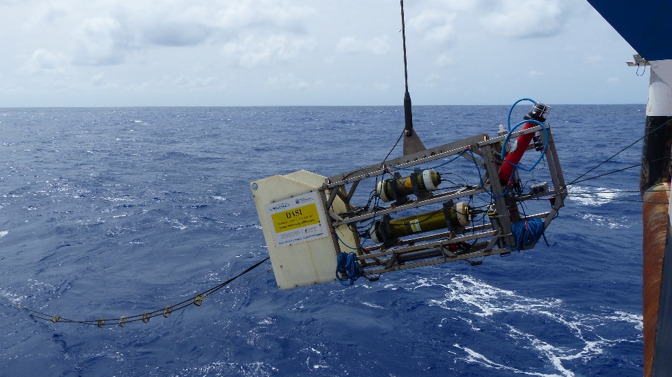
The University of Southampton has owned a transmitter source since the 1990s (designed by Martin Sinha) which is shown during a deployment in Fig.1 (more information can be found here)
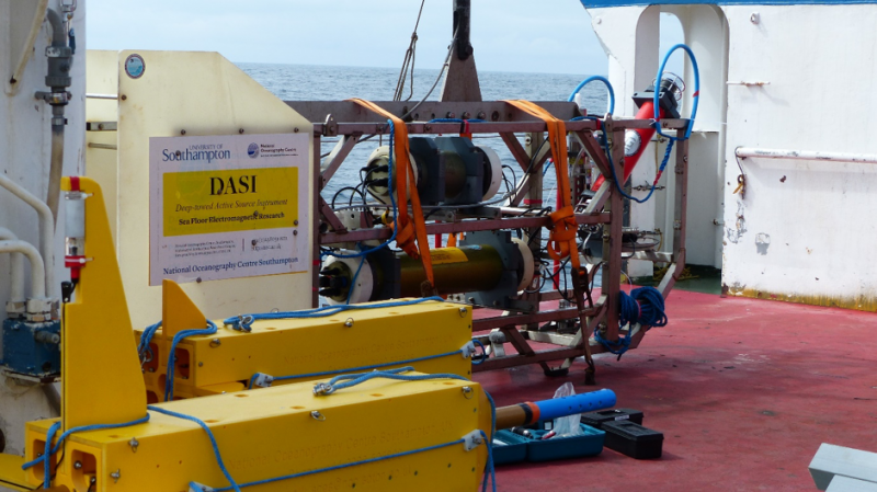
 electromagnetic group at Scripps Institute of Oceanography which are shown prior to a deployment in Fig. 2.
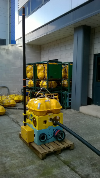
 Ocean Bottom Electric (OBE) instruments will also be deployed on the seabed. The UK Ocean Bottom Instrument Consortium (OBIC) are currently preparing twelve OBE instruments measuring the horizontal as well as the vertical component of the electric field. For the design of the vertical arm we collaborate with the electromagnetic group at Scripps who have already successfully deployed seafloor instruments with three components. Scripps also provide us with eight data loggers to record data at a lower amplification. An example of one of the instruments under construction by OBIC is shown in Fig. 3.